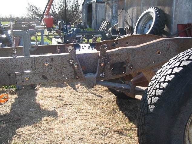
| To get the frame to sit level I moved the front hangers
straight up 3".
|
|
|
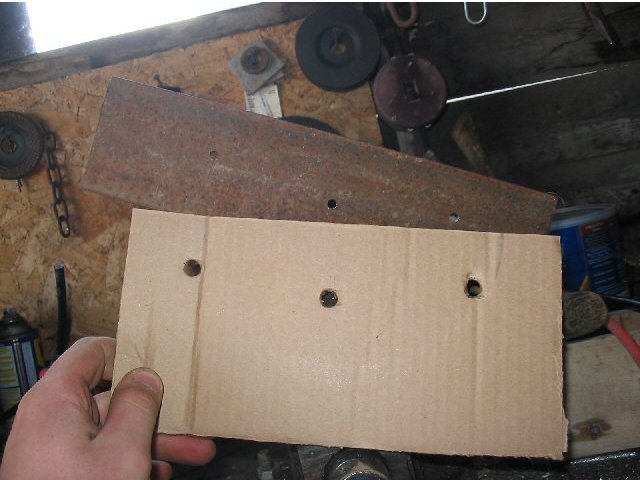
| Now use your cardboard template to mark and drill the
three holes in the 12" angle iron pieces.
|
|
|
| I reamed out the top crossmember bolts to fit 1/2 bolts
and I have also bolted the front portion of the frame together.
|
|
|
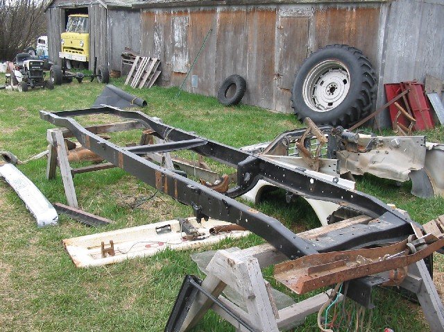
| You can now weld the frame together. If your not
comfortable welding this part you can have a professional or friend
do it for you. I used an old Forney 220 amp arc welder. I
used 7014 rods at 90 amps. I welded it fully on the outside of the
frame and only welded the horizontal joints inside because if you
weld the vertical joints, the weld may crack when the frame flexes.
|
|
|
| You will need to strip all the body mounting brackets off the 48-52 frame.
|
|
|
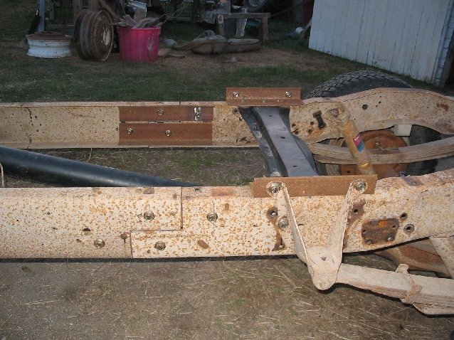
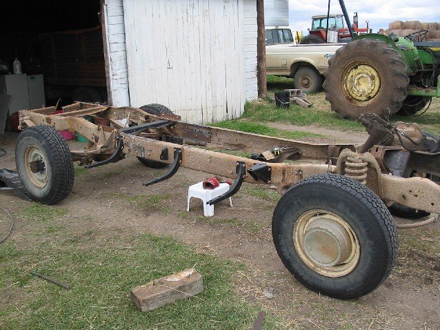
| Use a plumb bob to find the rear axle center line and mark it on
the frame. The 48-52 frame has a small hole above the rear axle which is the axle
center line. Now take precise measurements from the 48-52 frame and drill the
required holes in the Supercab frame to mount the body mounts as shown above. I
found I had to mount the front running board mount back 1 1/2" due to the
transmission crossmember mount rivet was in the way. Also the rear running
board mount is ahead about 2 1/2" due to the truck having longer rear leaf springs.
You will have to cut 1/2" off the end of the middle cab mounts for the cab to fit.
|
|
|
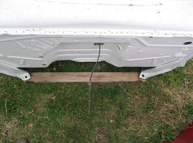
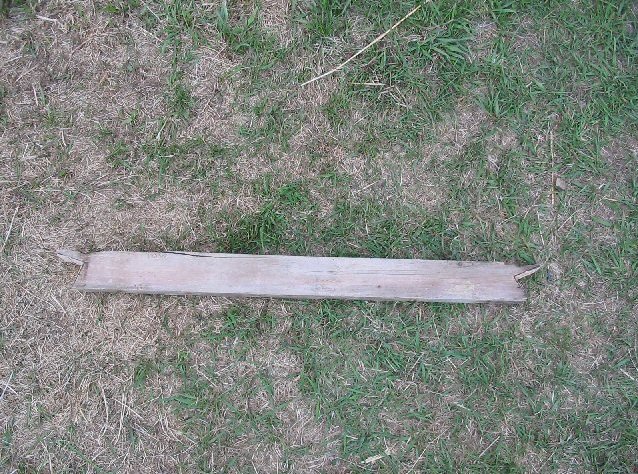
| Take a 2x4 and draw around the front cab mounts.
|
|
|
| Cut out the area you just marked on the 2x4.
|
|
|
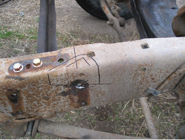
| These next couple of steps take your time as you will get
better results. Measure where the front cab mounts are on the 48-52 frame and
transfer it to the Supercab frame. Note the line on the top rail. Take a
measuring square and lay it flat on top of the other middle cab mount. Mark a
straight line as shown.
|

|
|
| Lay the 2x4 template you made of the front cab mount on the
frame and trace the outline on the frame. Take one of the pieces you cut out
of the frame and position it a little ways behind that one and draw as shown.
I drilled 1/4" holes in each of the corners so when you use your angle grinder
to cut it out you don't have to worry about cutting it out to far.
|
|
|
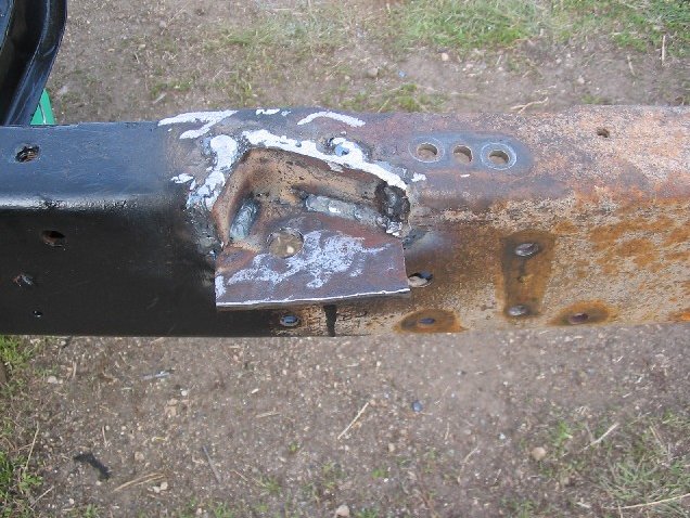
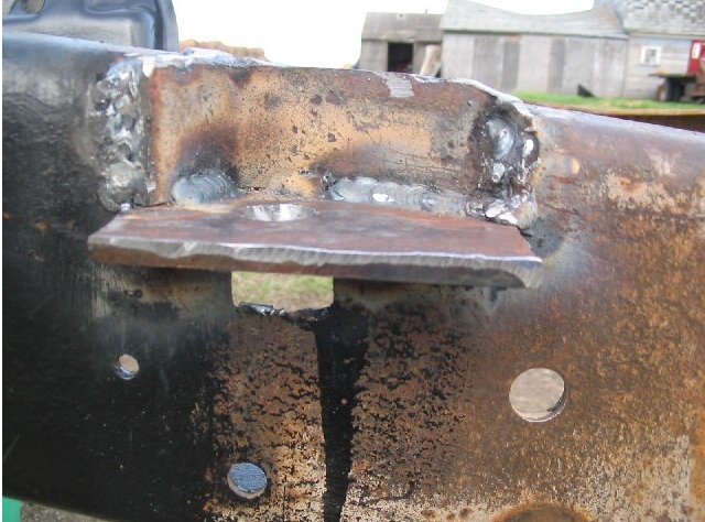
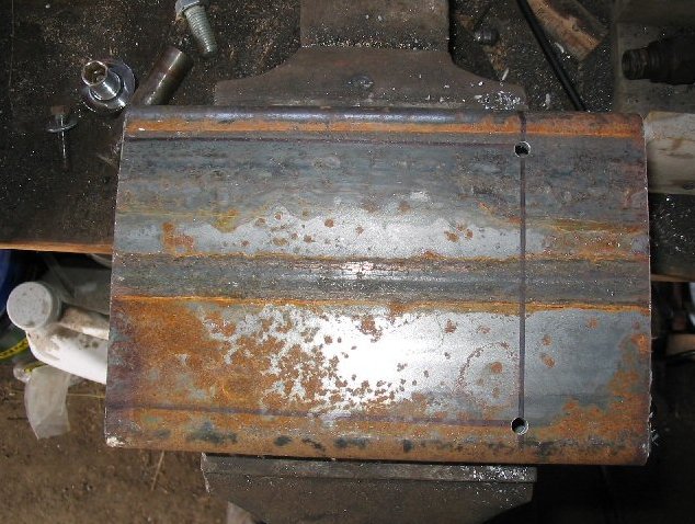
| I cut out a rectangular piece and a corner piece form one of
the frame sections you cut out earlier. I fitted them in the frame and marked
the two pieces. I then welded them together in the vise. I notched the frame
under where the hole will be. I then welded the mount into the frame and drilled
a 3/4" hole over the notch.
|
|
|
|
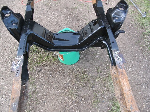
| Now repeat the previous steps for the other side. You should
have something that looks like this.
|
|
|
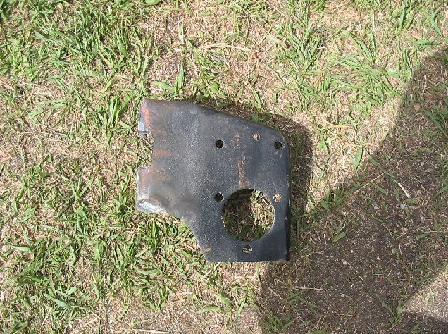
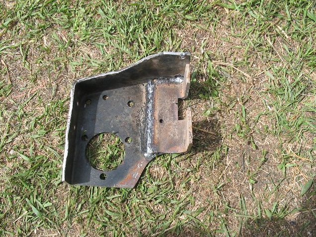
| Remove the PASSENGER side master cylinder mount from the 48-52
frame. I cut off the original side mounts and the bottom ones too. I then welded
a 2 x 2 x .25 angle iron to the side and I notched out the side to match the
original one. I drilled out the pedal assembly mounting holes to 1/2. I clamped
it into the frame right against the front of the transmission mount. I found I
could reuse two holes out of the middle cab mount. I then drilled a 1/2 hole
through the top of the frame rail into the top of the bracket.
|
|
|
|
|
|
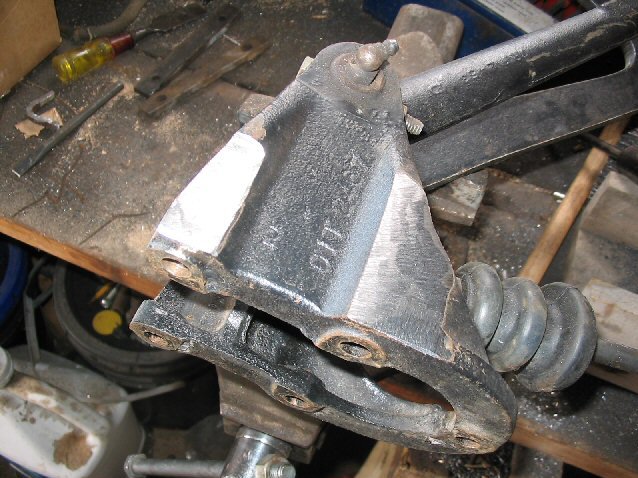
| To make the pedal assembly to fit you will have to grind a
little off the edge to the pedal assembly as it wasn't originally meant to mount
on the back of the bracket. It doesn't take much grinding so you aren't
compromising the integrity of the cast piece.
|
|
|
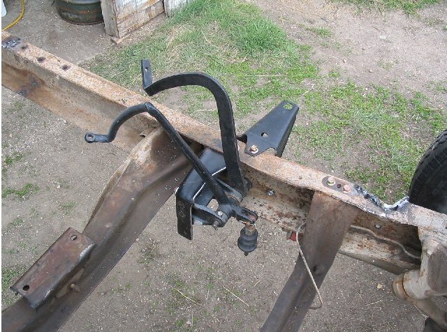
| Here you can see the pedal assembly and bracket mounted in the
frame. Not pictured but I later removed the clutch pedal due to the fact of it
serving no purpose since I'm using an automatic.
|
|
|
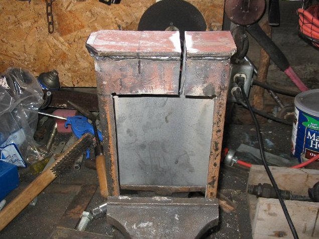
| Cut a 9" piece of the rectangular tubing. I measured 2" from
the end and 3/4" from the sides. I drilled a hole in the corners to provide room
when cutting the corners.
|
|
|
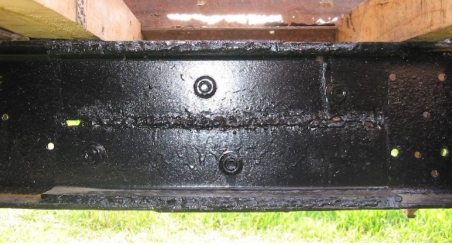
| Here you can see that I have cut out the center, welded an end
cap and notched it 2" from the bottom of the rectangular tubing to allow it to
fit the frame rail. You have to grind out the cut to 1/4" wide.
|
|
|
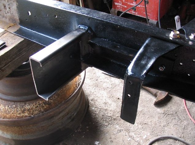
| I slid the booster mount right up to the back of the transmission
mount and onto the frame rail. I took a measuring square to make it perpendicular
to the frame and then welded along the bottom of the frame rail. I bolted it
through the end cap.
|
|
|
|
|