| Take a long punch and use it to mark the center of the pedal
mount to the booster mount. Take a tape measure and make sure you mark is exactly
center. Drill an 1/8" hole.
|
|
|
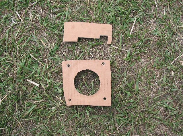
| Make some cardboard templates of the booster's mounting holes
and the side profile of the booster.
|
|
|
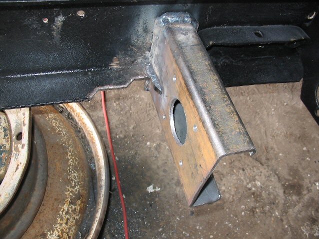
| Use a 2 1/2 hole saw and cut out the circle using the 1/8"
hole you made earlier as the center. Then use your cardboard templates to mark
the booster mounting holes and where you need to notch the frame to make the
booster fit. I cut the corners off on the frame notch to make booster mounting easier.
|
|
|
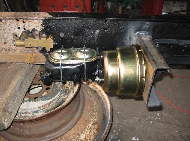
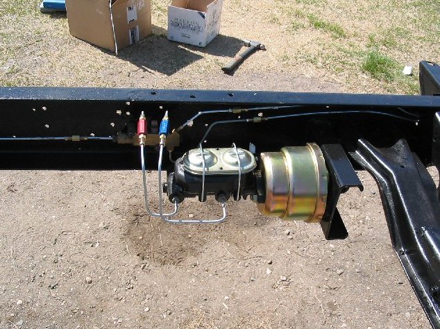
| Here I have bolted the booster and master cylinder onto the
bracket. Note: the Supercab proportioning valve on the left. I'm using an
aftermarket 1" bore master cylinder and 7" dual diaphram booster.
|
|
|
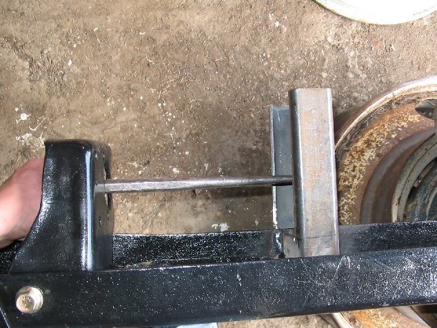
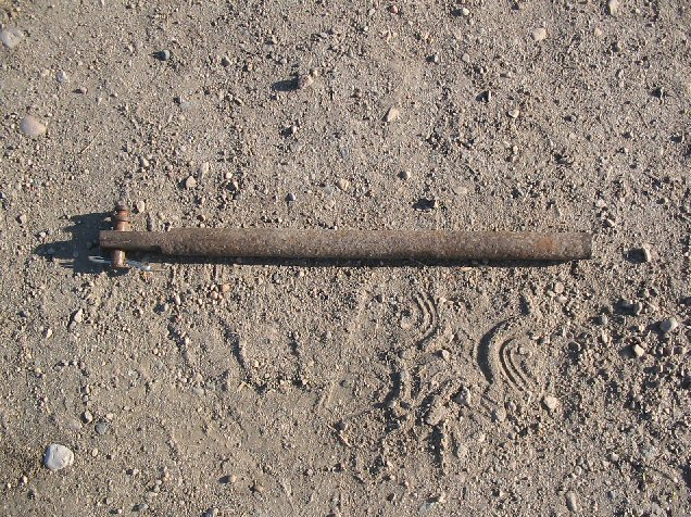
| Here is the shaft I made to connect the brake pedal to the
booster. It is a 3/4" rod that I have ground down one side to fit the pedal and
drilled a hole into other side which I have tapped with the correct threads to
. fit the booster. The length will vary on what booster you use and design.
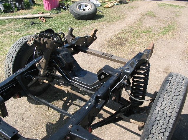
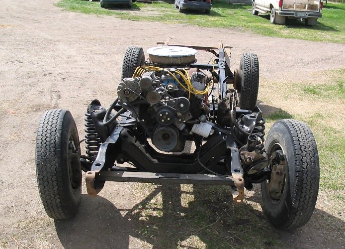
Now is a good time to replace all the bushings in the front suspension while
there is no weight on it and to paint it.
|
|
|
| You can see how I have routed the front brake lines copying
the factory design.
|
|
|
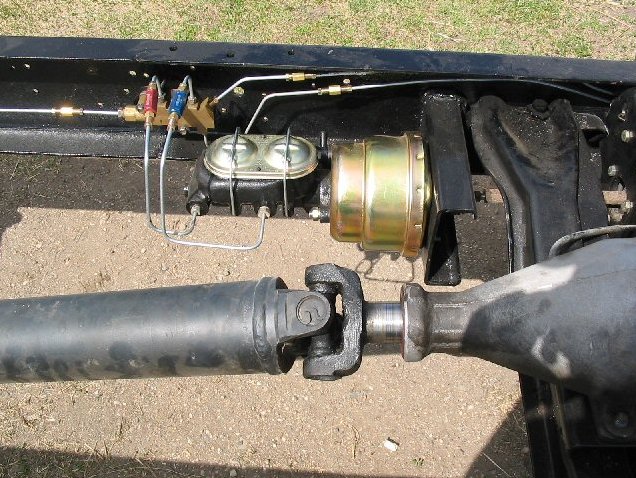
| This is how I plumbed the master cylinder to the proportional
valve. The colored connectors are residual valves which are required when
mounting the master cylinder under the floor so brake fluid doesn't run back
into the master cylinder. Note: I haven't plumbed in a stop lamp switch yet but
it is easily added.
|
|
|
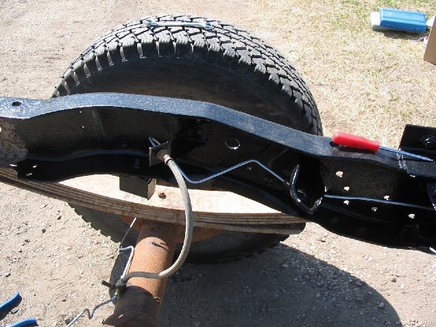
| This is how I bent the rear brake line.
|
|
|
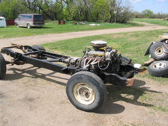
You can put the engine and transmission into the frame now.
If you're using a different engine than what came with the truck you will need
to get the correct engine perches for your particular engine.
240 / 300 I-6 use the same engine perches and mounts.
302 / 351W / 351M / 400 use the same engine perches but the 302 / 351W uses
different engine mounts than the 351M / 400 engines.
352 /360 / 390 use the same perches and mounts.
429 / 460 use the same perches and mounts
I'm using an 302 and AOD transmission.
|
|
|
|
| You will have to get a driveshaft made or cut to fit the
shortened chassis. You want about 3/4 to 1" of yolk play. The driveshaft place
will help you get the correct measurements as it is very tricky to get the
correct length. Don't ask me how I know. Also length will vary on transmission
and differential choice.
|
|
|
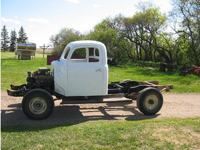
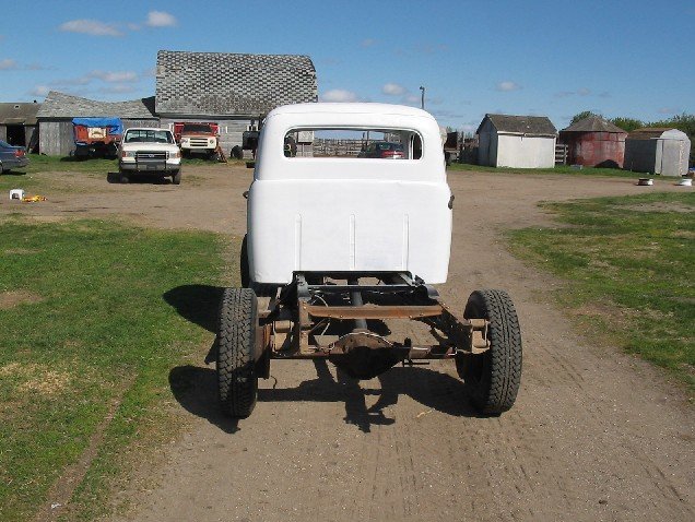
| You can know set the cab onto the chassis. It will take some
jacking and cab.
|
|
|
|
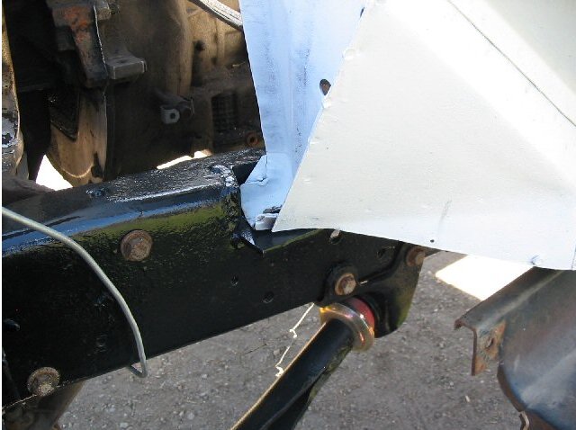
| See how good measuring pays off. The front cab mount slid right
into place and the hole lined up perfect. I still have to put the rubber bushing
in. The middle cab mount hole will have to be redrilled due to the fact that is
sits farther back and the cab hole is farther in on the mount.
|
|
|
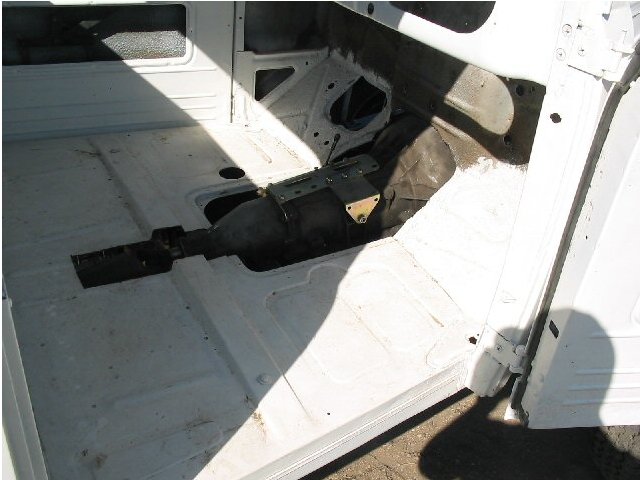
| You will have to do a far amount of trimming to make the cab
fit as the engine sits a lot higher than the old flathead V-8. You will have to
make a new transmission tunnel.
|
|
|
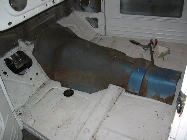
| I cut the floor out of a '73 Ranchero and have trimmed it to
fit the cab. Any '70s Ford car should work. I still have do some work to do
before it looks factory.
|
|
|
| Take some more measurements from the 48-52 frame for the
radiator mounting holes. You will have some radiator clearance issues if you use
the back radiator mounting holes. I've welded the 3" C channel into place and have
drilled the mounting holes for the radiator.
|
|
|
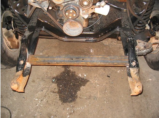
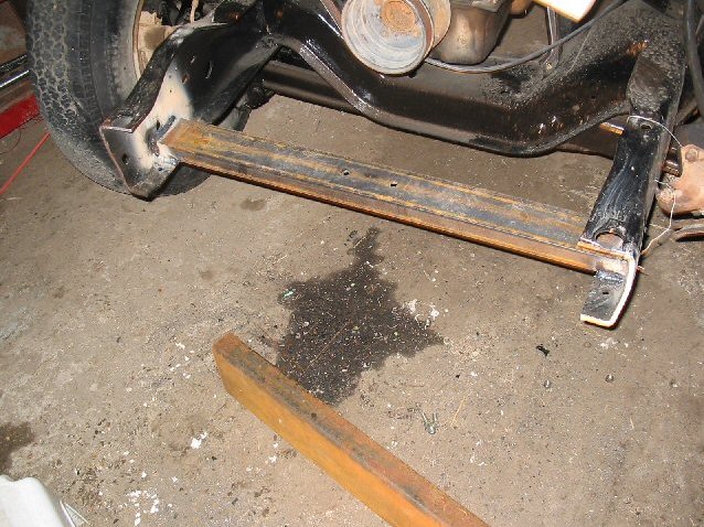
| In order for the front sheet metal and bumper to fit, the
Supercab bumper mounts have to go. I found cutting just in front of the bushing
mount hole leaves enough room for the sway bar mounting brackets.
|
|
|
| With the front bumper mounts gone you can start the front
frame modifications.
|
|
|
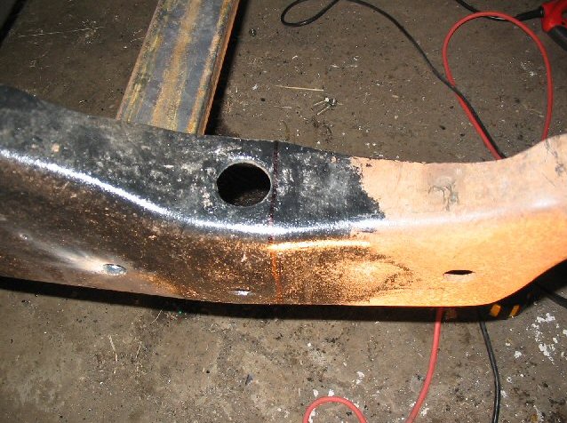
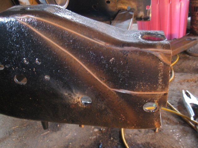
| As it stands now the frame rail is too tall for the front sheet
metal to fit so it must be trimmed. Here is what I will be cutting out to make
the frame rail sit lower.
|
|
|
|
|